25+ component diagram in software engineering
It models the physical view of a system. Myself Shridhar Mankar a Engineer l YouTuber l Educational Blogger l Educator l Podcaster.
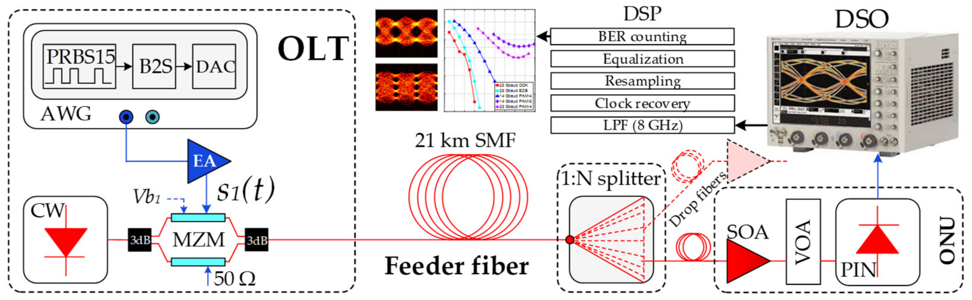
Applied Sciences Free Full Text Optical Power Budget Of 25 Gbps Im Dd Pon With Digital Signal Post Equalization Html
A Component contains information about the logical Class or Classes.

. Compare. The levels begin from 0 1 2 and so on. This software component diagram template can help you.
A component diagram allows verification that a systems required functionality is acceptable. Component-based development CBD is a CBSE activity that occurs in parallel with domain engineering. Component symbols are rectangles.
0-level DFD provides a brief overview of the software requirements as a single. - Simplify interactions within complex systems. A component diagram is used to break down a large object-oriented system into the smaller components so as to make them more manageable.
My Aim- To Make Engineering Students Life EASYWebsite - https. Up to 24 cash back Pre-drawn UML component diagram symbols represent component package package container dependency generalization tranparent stereotype. Using analysis and architectural design methods the software team.
25 UML Component Diagrams A UML component is a modular replaceable unit with well-defined interfaces. These diagrams are also used as a communication tool between the developer and. Winter 2009 Maheswaran Introduction to.
Component Diagram UML Compute. - Display the structural relationship of software systems and their elements. Component diagrams are often drawn to help model implementation details and double-check that every aspect of the systems required functions is covered by planned development.
Data Flow Diagrams YC Database. Up to 24 cash back UML Model Diagram is ideal for software developers and program managers who need to illustrate and interpret software application relationships. Below are the 3 important levels of DFD.
UML Class Diagram in Software Engineering. Define the structure of a software system by describing the system classes their attributes and the relationships among them. INTRODUCTION UML component diagrams describe software components and their dependencies to each others A component is an autonomous unit within a system The.
A Component diagram represents pieces of software in the implementation environment in terms of code components.
How To Simplify A Complex And Frustrating Change Management Process When Delivering Software To Production Quora
Shared Repo A Tale Of Evolution By Alex Ewerlof Medium
1
1
1

Iterations Of Score Indicators Data Visualization Design Scores Data Visualization

Simple Architecture Diagram Uml Template Mural
1

15 Awesome Css Flowchart Examples Onaircode Flow Chart Software Development Life Cycle Workflow Diagram

15 Awesome Css Flowchart Examples Onaircode Flow Chart Software Development Life Cycle Workflow Diagram

Pin On Web 大数据

15 Awesome Css Flowchart Examples Onaircode Flow Chart Software Development Life Cycle Workflow Diagram

I Made A Disassembly Schematic For The Iphone 6 Infos In Comments Iphone Apple Iphone Repair Iphone Solution Mobile Phone Repair

How Do We Innovate The Component Industry From What It Already Is Can We Passive House Passive House Design Passive Solar Design

React Tree View Component Examples With Code Onaircode Coding Binary Tree Tree Structure

It Asset Management Infographic Asset Management Management Infographic Tracking Software

Top 25 Microservices Interview Questions And Answers